Intelligent Smart Grid Liquid Cooling
Intelligent Smart Grid Liquid Cooling
Never before has responsible energy been more important. As economical, social, and political realities converge, smart grid technology is moving to the forefront of the industry. DSI Ventures examines the importance of Smart Grids that utilize the power of IT and environmental technology as well as the role that liquid cooling will play as these systems increase in complexity and heat management becomes more critical to success.
By Jason D. Carr
Introduction
Today, energy policy is being driven by political, economic, market, and environmental pressures. As power is being driven by unprecedented demands worldwide, new business models and technologies are emerging to cope with these pressures while maintaining efficiencies and competitiveness. Smart Grid technology is quickly becoming recognized as the most effective way to solve these issues in multiple industries such as utilities, government, IT, and more. For example, Smart Grid technology has emerged allowing utilities to accurately manage consumer demand for power while at the same time accomplishing long-term business goals. In this paper, DSI examines the technological demands inherent in Smart Grid technologies. We examine the current Smart Grid environment and its impact on the world. Finally, we discuss the cooling issues inherent in Smart Grid environments and the important role that liquid cooling will play in this promising technology.
Smart Grid – Where We Are Today
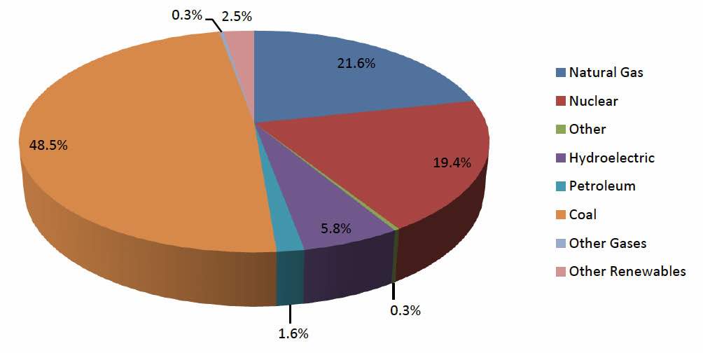
Thomas Edison first envisioned a distributed system of power delivery late in the 19th century however a centralized system was chosen over Mr. Edison’s vision and is the method of power delivery today. The problem with the centralized system is that it is unable to economically and viably handle the enormous energy demands (see Figure 1 below) of the world today over the long-term. Serious challenges now threaten our power supply worldwide. It is our opinion that Mr. Edison’s vision must become reality and this is accomplished via Smart Grid technologies. Smart grid technologies involve more intelligent equipment, operations, transmissions, and utilization systems. This essentially means that megabytes and bits will become as important in the world of energy as megawatts and atoms. By utilizing new and existing technology, along with advances in energy, our world will be positioned to handle ever-growing power demands. Obviously, as this transformation occurs, faster and more powerful systems will be required and will entail smart cooling management.
Figure 1. US Electric Power Industry Net Generation, 2007
Green Change
As discussed above, the current demand for power and the available supply is adversely affecting energy pricing and availability. Energy conservation is increasingly becoming an important agenda item for utilities and governmental agencies worldwide. With the notion of conservation comes the need for alternative energy sources as well as climate saving technologies. The public is increasingly pushing for green energy and this in turn is leading politicians and lobbyists to push legislative reform. This includes far-reaching initiatives such as carbon emission reductions and new energy based requirements. Consumers are seeking eco-friendly products and services while companies are increasingly being pressured to reduce pollution and environmental impact. Power consumption by servers, data centers, and other IT systems continue to grow annually. All of these issues are present today and the green movement is full-speed ahead. That being said, integration of the smart grid with renewable energy systems is still a formidable issue. While the smart grid is certainly more efficient than today’s grid, it does not integrate with renewable energy services although many companies are working to change this. Eventually, the smart grid will need to evolve and embrace the openness of renewable energy systems, which already have the capabilities to sync and integrate with many other renewable energy systems via open energy management solutions. All of these systems, as stated earlier, will require effective cooling management.
Traditional Cooling Methods
As the systems required to effectively manage the Smart Grid grow in complexity, so too will the cooling requirements. This has become apparent in the data center environment and will become even more so with the rollout of a national grid system. Liquid cooling is a viable cooling option as enhanced fluids have been introduced in recent years. One such fluid is DSI’s Opticool Fluid solution. To better understand how these enhanced fluids may be the best option for the Smart Grid, one must first understand the cooling options available today.
Air:
Traditionally, forced air has been the primary cooling choice for IT systems. Air is inexpensive, easy to move, non-toxic and a good insulator, so the circuitry being cooled does not require additional dielectric insulation. Air, however, is not very efficient in transferring heat, due to its relatively low heat capacity (specific heat). Simply put, air doesn’t hold as much heat and it therefore takes a lot of air blowing across a hot part in order to cool it. Air does not normally have any problems, though, with health, safety and the environment, nor with material compatibility.
Standard Mineral Oil:
Standard equipment oil and other mineral oils have been used in the past, but haven’t been widely used for several reasons. Although they’re efficient in transferring heat away from a circuit board, they typically have low biodegradability and there are often problems with material compatibility. Many mineral equipment oils, for example, are excellent solvents, so they have a problem with delaminating circuit boards or dissolving rubber parts. Standard mineral oils are usually not highly biodegradable, and often cause acne or other allergic reactions on the skin of those who work with it.
Fluorinated Fluids:
Fluorinated fluids, such as Freon®, are excellent heat transfer fluids. They have a very high specific heat, low viscosity and usually have good material compatibility. Fluorinated fluids are normally very expensive, however, and many have been discontinued because of concerns that their vapor can combine with ozone in the upper atmosphere, thereby depleting the ozone layer above the earth. Some fluorinated fluids can also decompose under an electric arc to create HF, hydrofluoric acid, which can be dangerously aggressive.
Vegetable Oils:
There are several vegetable oil-based fluids on the market now; their primary advantage is that they are highly biodegradable and environmentally friendly. Vegetable oils have satisfactory specific heat values, but their higher viscosity (the highest of the different liquids discussed here) often prevent them from being as efficient in heat transfer as a lower viscosity mineral oil. Most vegetable oils do not have the same oxidation resistance as mineral oils.
Synthetic “Petroleum” Fluids:
There are fluids that combine the best of many of the other types of oils available, without the associated drawbacks. These fluids are synthetic hydrocarbons – synthetic petroleum, if you will. Synthetic paraffinic hydrocarbons, such as isoparaffins and poly alpha olefins (PAOs) have high biodegradability, low flammability, and low toxicity. They have excellent resistance to oxidation, which makes them ideal for use as original fill fluids in electronics and industrial heat transfer systems.
Intelligent Liquid Cooling
OptiCool Fluid is a proprietary synthetic petroleum based cooling fluid specifically designed for electronic circuitry and IT systems such as those found in Smart Grid environments. With very low viscosity, OptiCool cools equipment better than petroleum or vegetable oils and has EXCELLENT heat transfer characteristics. It’s highly biodegradable – just as environmentally friendly as the vegetable oils are – and it has a service life that’s longer than petroleum.
Conclusion
Smart Grid technology is reshaping the energy marketplace. The Obama Administration’s New Energy for America plan calls for a $150 billion investment in clean energy systems, the creation of 5 million new jobs, the manufacture of 1 million plug-in hybrid vehicles by 2015, greenhouse gas emission reductions (80% reduction by 2050), and the generation of 25% of the nation’s power from renewable resources by the year 2025. Meeting these lofty goals will require enormous IT system investments across the board and along with these systems will follow the enormous cooling challenges. DSI helps solve the cooling obstacle through advanced liquid cooling solutions such as Opticool Fluid. Customers can utilize this intelligent liquid cooling solution to meet a number of strategic Smart Grid challenges including cost savings, improved heat transfer, green objectives, and more.
Notes:
“Insulating Materials for Design and Engineering Practice”; F.M. Clark
“A Study of the Relationship Between Insulating Fluid Viscosity and Equipment Cooling Performance”; Dr. D. Sundin
“Electrical Insulation”; British Institute for Electrical Engineers
Whitehouse.gov, American Recovery and Reinvestment Act, February 17, 2009
Discussion on Specific Heat
Heat Capacity:
 One of the most important characteristics of a good heat transfer medium is a high heat capacity, or “specific heat”.
What, exactly, is the heat capacity of a material, and how does it affect cooling of a circuit board or in a data center? Heat capacity is an intrinsic characteristic of a material, and refers to the amount of heat, measured in joules or calories, that must be input into a material in order to raise its temperature by a certain amount. Different materials hold different amounts of heat (again, measured in joules or calories), even when they’re at the same temperature. Think of heat capacity as the “thermal mass” of a material, if you will.
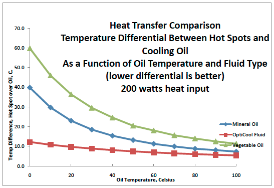
A heat capacity means that a relatively small mass of fluid carries a large amount of energy away, per unit temperature drop. A fluid with a lower heat capacity would need a greater temperature drop or greater flow rate with more heat exchanger surface to transfer the same amount of heat away.
A good analogy is to think of standing in 65-degree air – it’s pretty comfortable. But if you jump into a swimming pool at the same 65 degrees, the water feels really cold. That’s because air has a low heat capacity, and doesn’t hold much heat. It doesn’t draw heat from you or transfer heat to you very well either. The temperature of air rises a few degrees with only a few joules of energy input, so it’s not a very good heat transfer medium. Water, however, has a high heat capacity, and can absorb a lot of energy before its temperature rises. When you jump into the 65 degree pool, it feels much colder than the air did because the water pulls the heat away from your body more efficiently. And so it is with heat transfer media; a high heat capacity makes for more efficient heat transfer, all other things being equal. When using a heat transfer medium that has a low heat capacity, a lot more of the medium has to be used to pull the same amount of energy out of the circuitry.
News: 230 kV Beta Fluid Transformers Energized in Mexico
January 15, 2015
TYLER, TX – DSI Ventures, Inc. announces the commissioning of two 230 KV Generator Step-Up (GSU) Transformers filled with Beta Fire Resistant Fluid at the new Bajio thermoelectric power plant in Guanajuato, Mexico.
Installed in 80 and 150 MVA, 230 KV transformers built by Hyosung Nantong Transformer Company, Beta Fluid was chosen for its 22 year record of fire safety, its low price and its excellent environmental record.

Beta Fluid is a fire resistant transformer oil made from petroleum base oils. Developed in 1993, Beta Fluid has been used in tens of thousands of applications worldwide to add a significant margin of safety to transformers located in hazardous locations.
“Although the majority of Beta Fluid applications are distribution or small substation transformers, Beta Fluid can be used even at the highest voltage levels, with no changes in electrical or insulation design”, stated a representative of DSI Ventures, manufacturers of Beta Fluid. “It has excellent impulse strength and the same dielectric constant as standard mineral oil. Beta uses the same Dissolved Gas Analysis and other maintenance procedures as mineral oil, which is another factor in the decision to use it in power transformers”.
Stop Corrosive Sulfur: A Successful, Multi-Directional Approach
Stop Corrosive Sulfur:
A Successful, Multi-Directional Approach
DSI Ventures, Inc.
Abstract:
Corrosive Sulfur in transformer oil has been the cause of high profile transformer failures in recent years. Oil treatments consisting of copper passivators have been only partially effective. DSI has discovered a multi-step method that has been proven to change oils with corrosive sulfur into non-corrosive status, as well as significantly slowing oxidation and ageing of insulating oil and paper. This paper outlines the history of the problem as well as the research that led to a successful commercial launch of a product known as DSI Sulfur Inhibitor.
Background:
Corrosive sulfur has recently received a great deal of attention by owners of power transformers. Before the mid-1990s, however, it was considered a phenomenon that occurred only with transformer oils of questionable quality. The consensus was that if one used one of the major brands of oil that this problem would rarely be encountered. Many things have changed in the last two decades, however, to make the problem of corrosive sulfur a very real one:
- Refining and oil purification methods have changed.
- The transformer oil industry has seen many oil suppliers leave the market, shifting market share to new suppliers.
- Sources of crude oil have changed; new sources contain different profiles of naturally occurring sulfurous compounds.
- Transformer operating conditions and designs have changed. Today’s transformers are designed with less cooling oil with respect to the mass of metal available, which raises the relative level of metal ions in the oil.
- Modern transformers, too, are being operated at higher temperatures, which has several effects.
- Higher temperatures seem to have the effect of changing a type of sulfur from non- or poorly reactive one into a type that is more highly reactive.
- Higher temperatures drive chemical reactions to occur at a faster rate which means that the dissolution, reaction and plating effects of sulfur-metal compounds occurs much more quickly than it would have in the past.
Types of Sulfur Compounds
Not all sulfur compounds in oil are harmful. Some are not only stable, but actually have antioxidant effects. Others, such as mercaptans, simple sulfides and elemental sulfur are highly reactive. Dibenzodisulfide (DBDS) is thought to be one of the more reactive sulfur species that is found in transformer oils. The types and quantities of sulfur in an oil depends on the source of the crude oil and the refining methods used. Different crude oils have different amounts of each of these sulfur compounds. Different companies’ refining processes can remove or change sulfur compounds from one type to another.
What Happens With Corrosive Sulfur?
Inside a transformer, metals – copper, iron and aluminum, slowly dissolve into the transformer oil. Because of its molecular structure and properties, copper is the most easily dissolve and the most reactive of the metals normally found in transformers. Metal ions in solution combine with sulfur compounds to produce a range of copper-sulfur salts. The exact profile of the metal-sulfur salts that are created depends on the conditions inside the transformer, the types of copper that are present, and the types of sulfur that is present in the transformer oil.
But copper isn’t the only metal that can take part in chemical reactions. The different alloys of aluminum and iron that are found inside a transformer also dissolve into transformer oil, and their ions can and do interact with sulfur. If copper isn’t present, aggressive sulfur will combine with these other metals to form a variety of sulfur-metal salts.
These sulfur-metal salts, whether they’re from copper, iron, or aluminum, saturate the transformer oil. When the concentration of salts reaches a certain point (which varies, according to the chemistry of the oil and the conditions in the transformer), the salts will grow in a crystalline structure on other surfaces inside the transformer. These surfaces may be paper, wood, or any surface that can act as a substrate to the growth of copper-sulfur, ferro-sulfur, or alumino-sulfur salts.
This process repeats itself 1 until the source of metal or sulfur ions is used up. Before this happens, however, the transformer will often experience problems because the metal-sulfur salts that are being deposited (“plated out”, in common terms) are conductive. The buildup of these conductive salts leads to transformer failure.
What can be done about this? Studies have shown that sulfur is difficult to remove from transformer oil. Filtration with fuller’s earth or other ion exchange media has very little effect on the concentration of sulfur compounds, although it can remove some of the metal-sulfur salts that are already in solution.
The Traditional Approach
Historically, corrosive sulfur has been dealt with not by treating the sulfur, but by hindering copper ions from entering solution. This can be done by using a variety of “Yellow Metal Passivators”. These Yellow Metal Passivators, such as benzotriazole, or tolyl-triazole, form a very thin, non-reactive coating on copper and thereby slow its dissolution into transformer oil.
There are three problems with attempting to stop corrosive sulfur with the simple addition of a yellow-metal passivator, however.
- There are several different alloys or varieties of copper and brass materials in every transformer. Each different type reacts differently with different copper passivators. Some are very well protected by one chemical passivator, but not another. Some don’t bind well to either type.
- Different iron, steel and aluminum metals are present in transformers,and they are also are reactive to aggressive sulfur. While they’re not as reactive as copper, they do combine with sulfur and have a hand in the plating reactions that occur. Copper passivating chemicals – benzotriazole and tolyltriazole – don’t protect transformers from reactions involving iron, aluminum or steel.
- Copper passivators, by themselves, don’t do anything to reduce the corrosive sulfur compounds in transformer oils. They simply attempt to intervene in the dissolution of certain metals. The underlying corrosion problem is still present.
Physical Removal of Sulfur:
Several attempts have been made to find a way to physically remove sulfur from transformer oil. Sulfur is very difficult to remove, however, from existing transformer oil. Filtration with fuller’s earth or other ion exchange media has very little effect on levels of sulfur found in oil.
Chemical Removal of Sulfur:
Research at DSI has found that aggressive sulfur compounds in transformer oil can be changed by introducing them to one of several reactive “sulfur scavengers”. These compounds “tie up” sulfur in oil, preventing its reaction with any metal ions. The sulfur-metal salts are effectively prevented from forming, so they can’t “plate out” onto cellulose insulation.
These sulfur scavengers are large, complex molecules that are especially reactive to corrosive sulfur compounds, but not to other chemicals found in transformer oil. They effectively combine with reactive sulfur and hold it in suspension, preventing it from combining with metal ions in oil. Analysis has shown that some of the more aggressive types of sulfur, such as dibenzo-disulfide (DBDS) can actually be changed to a less aggressive compound of sulfur.
Relationship Between Corrosive Sulfur and Oxidation:
Field and anecdotal evidence describes a correlation between low oxidation resistance of an oil and its propensity to develop problems with corrosive sulfur, given the same application conditions. While the basis for this correlation is not well understood, it has been noticed and discussed at CIGRE and IEEE, and was considered significant enough to take into account during this investigation.
Commercial Development and Application:
In 2006 and 2007, continuation of this research program resulted in the development of a commercially available product to protect transformers from corrosive sulfur in transformer oil.
This new sulfur protection and reduction scheme protects transformers in three different ways, which work in synergistic manner:
- First, DSI Sulfur Inhibitor uses a blend of several different metal passivators. Our research has found that a mixture of metal passivators are much more effective at preventing dissolution of copper into oil than a single compound. A years’ worth of study and laboratory testing yielded precise ratios for the use of different metal passivators that would prevent the different chemicals from interfering with one another, and to work together to protect the maximum number of types of copper metals found in transformers.
- Second, DSI exploited the causal link between oxidation stability of paper and oil and the ability of the sulfur-metal interaction to proceed. It is our understanding and belief that oils that have lower stability against oxidation are more likely to promote the dissolution of metal and its reaction with aggressive
sulfur compounds. For this reason, the product that we developed contains a powerful blend of different antioxidant chemistries that protect oil and paper from accelerated ageing and inhibits their ability to enter into chemical reactions. - Third, DSI developed a mixture of sulfur scavenging and passivating compounds. These chemicals seek out corrosive sulfur in oil and bind with it to prevent its interaction with metals, paper, or oil. The bound sulfur is effectively rendered harmless. The concentration of the most reactive types, such as DBDS, is actually lower after treatment with DSI Sulfur Inhibitor. This goes far beyond the protection provided by simple yellow metal passivators.
Taken together, these three mechanisms have been proven to be very effective in protecting metals and reducing the amounts and types of corrosive sulfur compounds found in transformer oil.
Laboratory Testing:
ASTM D1275b Corrosive Sulfur in Oil Test:
DSI Sulfur Inhibitor was first tested with four different oil samples that tested positive for corrosive sulfur. ASTM D1275B, which is the standard ASTM test for Corrosive Sulfur. This test measures the effect of subjecting clean copper strips to the oil being tested. We tested oil samples before and after treatment with DSI Sulfur Inhibitor. The oil samples were provided by different independent laboratories and the analyses were performed at a major independent laboratory.
Sample 1 Test result:
Untreated sample: 4b Corrosive
Treated Sample 3a Tarnished
Sample 2 Test result:
Untreated sample: 3b Tarnished
Treated Sample 3b Tarnished
Sample 3 Test result:
Untreated sample: 4c Corrosive
Treated Sample 3a Tarnished
Sample 4 Test result:
Untreated sample: 4b Corrosive
Treated Sample No Change (no corrosion or tarnish)
In each of the samples that had “Corrosive” status, DSI Sulfur Inhibitor changed the sample to “non-corrosive” status.
Dibenzo Disulfide (DBDS) Testing:
Dibenzo Disulfide is a chemical found in transformer oils that has been linked to corrosion of copper and other metals. Reduction in Dibenzo Disulfide (DDS) content of the oil is considered to be very closely linked to reduction in corrosive behavior.
Four samples of oil were treated with DSI Sulfur Inhibitor. Of these four, three had significant reductions in the concentration of Dibenzo DiSulfide. Some samples showed a greater reduction than others, but taken as an average, DSI Sulfur Inhibitor lowered the concentration of Dibenzo DiSulfide (DDS) in the oil samples by an average of 14250 ppb, or 26% of the DDS concentration of the pooled samples.
Field Application:
Since its commercial introduction, DSI Sulfur Inhibitor has been used in transformers (GSUs and substation units of several types) of varying ages and sizes. Results of oil tests on treated transformers have shown significantly lower dibenzo disulfide levels, lower oxidation rates, and enhanced protection for oil and paper. Transformer oil samples that have been tested have indicated that they are “non-corrosive” status.
Application Example:
A Chinese utility had two power transformers (Panyu 150 kV, 80 MVA) with oil that was extremely corrosive when tested with DIN and ASTM tests. A small sample of the oil was treated in the laboratory with DSI Sulfur Inhibitor, which rendered the oil “non-corrosive”. The utility then decided to treat both transformers with Sulfur Inhibitor. After treatment, the oil in both transformers tested “non-corrosive”.
DSI performed a full analysis on the oil from these transformers, before and after treatment. Analysis of the oil showed that the concentration of several corrosive sulfur compounds had been reduced or eliminated. For example, the concentration of 1-methyl dibenzothiophene had been reduced by 82% in one transformer and by 92% in the other.
How is DSI Sulfur Inhibitor used?
The completed DSI Sulfur Inhibitor is a pre-mixed, liquid concentrate blend of advanced passivators, oxidation inhibitors and sulfur scavengers and stabilizers.
It is added directly to transformers where there is corrosive sulfur or low oxidation inhibitor content.
Because DSI Sulfur Inhibitor is a liquid, it is simply added to a de-energized transformer. No further mixing or blending is required. As delivered, DSI Sulfur Inhibitor is dried, degassed, and highly processed. It is compatible with all brands of standard mineral oil and fire resistant petroleum oils.
DSI Sulfur Inhibitor is made for field application in transformers that are filled with standard mineral oil. DSI Sulfur Inhibitor is added to transformer oil to inhibit and prevent corrosion, plating, or other problems caused by corrosive sulfur. Although it has a blend of advanced antioxidants, sulfur inhibitor is not made to slow or reverse problems of “gumming”, polymerization, or premature oxidation of soybean oil dielectric fluids.
Acknowledgements:
DSI would like to acknowledge the contributions of Doble Engineering, Laboratories, TJH2B Laboratories, Rheinchemie Chemical Company, Lubrizol Chemical Company, Vanderbilt Chemicals, and Dow Chemical Company for their assistance in the realization of this work.
Minimizing CPU Overheating with Liquid Immersion Cooling
Minimizing CPU Overheating with Liquid Immersion Cooling
Jason D. Carr and David W. Sundin
DSI Ventures, Inc.
The Central Processing Unit (CPU) generates a great deal of undesirable heat in modern computing systems. The CPU is responsible for processing most of the data within systems and is often referred to as a computer’s central processor or simply processor. As data is processed within a system, heat is generated. Once heat thresholds are exceeded, CPUs are placed at risk of malfunction or permanent damage.
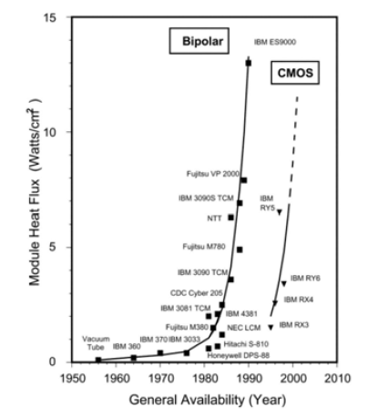
As microprocessors decrease in size, heat dissipation issues become increasingly prevalent. Moore’s law predicts the number of transistors placed on integrated circuits will double every two years. As CPUs continue to decrease in size while exponentially increasing in power each year, adequate cooling methods will increasingly become an integral part of new design planning efforts. Figure 1 shows the evolution of module-level heat flux in high-end computers over several decades. As shown, module heat flux has continued to creep upward with each passing year.
An experiment was conducted to evaluate liquid immersion cooling designed to mitigate CPU overheating through the use of a commercially available synthetic petroleum fluid, Opticool Fluid.
Issues with Air Cooling in Technical Applications
Air-cooling, which incorporates the use of fans, is currently the
prevalent method of cooling CPUs in computing environments. It has several advantages including reduced cost, relatively low noise, and is free of piping elements, tubes and cables.[2] The main function of fans is to pump air so that heat is effectively carried away from the CPU assembly. Air pressure can vary by incorporating fans in series (placed on top of one another) or parallel configurations (side-by-side).[3] The serial setup increases the discharge pressure while the parallel setup increases the area coverage. Based on several studies completed in recent years[1][2][4][5][6][7][8][9], air-cooling technology is insufficient to keep up with the growing requirements of CPU cooling in the marketplace.
Heat Transfer Overview
Fluid flow can be laminar (steady state) or turbulent, and heat might be transferred with and without phase change. In addition, the flow regime might be treated as Newtonian or non- Newtonian. Appropriate theoretical and empirical heat transfer equations have been developed for different velocity profiles, flow regimes and flow geometries. For the ideal case of fluid flow in a shell-and-tube exchanger, heat is transferred by radiation and convection to tubes via conduction through tube walls and by forced conduction from the internal wall surface to the bulk fluid.
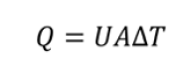 The basic equation governing all such heat transfer is where Q represents heat transferred in unit time, U represents overall heat transfer coefficient, A represents available surface area and ΔT represents temperature gradient between the source and the sink (or the inlet and the outlet). If multiple fluids or separating walls are used, then the overall coefficient U can be decomposed into individual coefficients h, each representing a particular medium.[10]
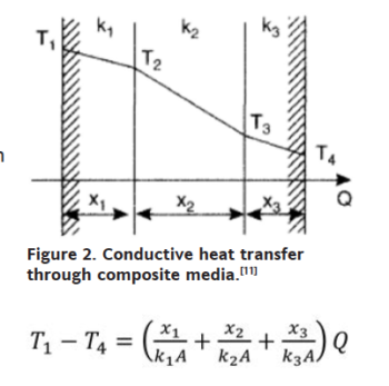
With reference to figure 2, the thermal gradient T1 – T4 is (right) where Q becomes the ratio of total driving force to total thermal resistance per unit area.[11] In instances of convective transfer, which is often the principal mechanism in liquid cooling, the heat transfer coefficient may be expressed as a dimensionless relation known as the Nusselt number, or as a dimensional equation. Convection is distinguished between natural (fluid movement caused by the transfer process itself) or forced (fluid movement caused by an externally applied force); in the former, the Nusselt number for external spaces is (left) where Ra, the Rayleigh’s number and Pr, the Prandtl number, are dimensionless numbers corresponding to the flow velocity and fluid properties.[12] 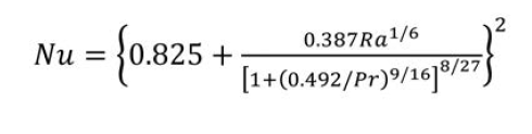 When we have steady flow of fluid past an immersed flat plate, two boundary layers develop. The first is hydrodynamic, within which velocity profile changes from 0 at the plate surface to flow velocity at the outer boundary; the second is thermal in which temperature profile changes from the plate surface temperature to the fluid temperature. These boundary layers are shown in Figure 3.
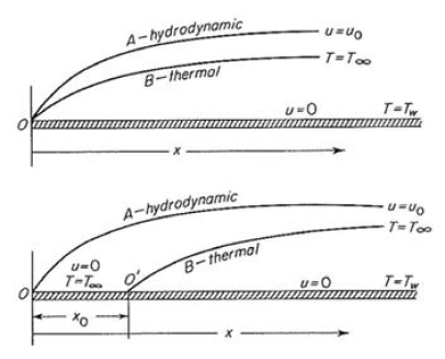
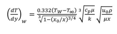
layers for steady flow of fluid past an immersed plate. Fluid temperature is T∞ and plate surface temperature is Tw; fluid velocity is u0. Entire plate is heated at top while there is an unheated length x0 at bottom.[13]
Raspberry Pi

Figure 4 shows the layout of the unit. The Raspberry Pi device is representative of ways that smaller component sizes are leading to more powerful computing. The device has been used for media streaming, home automation, and robotic applications,
to name a few[14]. The Raspberry Pi is typically powered by 5 V and 1 A 1.5 A and can be overclocked to a maximum
1,000 MHz. As with other computing devices, the Raspberry Pi tends to overheat when overclocked or when excess voltage is applied to the device. The maximum operating temperature for the Raspberry Pi CPU is 85°C As this experiment was conducted, the CPU never exceeded this temperature.
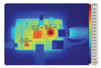
Figure 5: Thermal Image of Raspberry Pi Model B
The thermal image (Figure 5) shows that the CPU is one of the largest heat emitters when the Raspberry Pi is running at
normal capacity. During the study, CPU temperature measurements was exclusively focused on.
Experimental Design

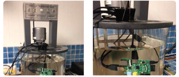
Figure 6. Raspberry Pi Model B
computing device with standard
5 V applied to power up.
The general layout of the experimental setup used for this study is shown in Figures 6 and 7. Baseline CPU temperatures were measured with standard 5 V input while unit was overclocked at 800 MHz, 900 MHz and 1,000 MHz respectively. Laboratory temperature was maintained at 20°C throughout the duration of the experiment. The immersion fluid was maintained at this same temperature during immersion testing as well. Measurements were recorded at device startup and in subsequent one hour increments. CPU temperatures were measured for both air cooling and immersion cooling with overvoltage levels of 6 V, 7 V and 8 V applied during three hour periods for each test, respectively. Overclocking speed of 1,000 MHz was maintained for the duration of the overvoltage testing. CPU temperatures were obtained via the Raspberry Pi unit itself by using the following command sequence upon login: /opt/vc/bin/vcgencmd measure_temp ENTER.
Results
During baseline testing, 5 V was applied to the Raspberry Pi Figure 4. Diagram of Raspberry Pi during three overclocking tests. Results were as follows: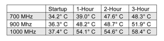
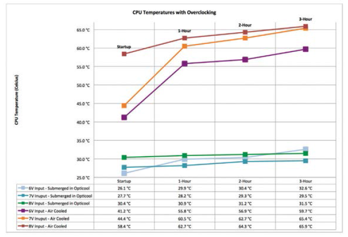
As shown, the maximum CPU temperature at 1,000 MHz after three hours of operation was 58.4°C. Next, temperatures were recorded as overvoltage was applied to the unit. Maximum overclocking of 1,000 MHz was maintained throughout. The results were recorded and graphed (Figure 8).
During 36 hours of testing, the device maintained adequate operation however when 7 V to 8 V was applied to the unit, operation became extremely unstable. This occurred during both air and liquid cooling testing. This is likely due to a limitation of the CPU used for this board, however based on these findings, on-board processor power of the Raspberry Pi can
be increased if a more powerful CPU were integrated into the design and combined with liquid immersion cooling.
Conclusion
As devices continue to shrink in size while increasing in power, performance improvements will continue to be plagued by increased power and cooling requirements. Furthermore, high temperatures negatively affect systems reliability as various components are exponentially dependent on operating temperatures. The results obtained during this experiment demonstrated how liquid immersion cooling can efficiently decrease CPU operating temperatures by as much as 50 percent or greater versus traditional air cooling. As discussed, thermal management will become increasingly important in the future. Liquid immersion cooling with Opticool is a viable solution that may be applied in any number of applications including data center environments, underwater ROVs and electric engines, to name a few.
[1] Chu, R.C.; Simons, R.E.; Ellsworth, M.J.; Schmidt, R.R.; Cozzolino, V., “Review of cooling technologies for computer products,” Device and Materials Reliability, IEEE Transactions on , vol.4, no.4, pp.568,585, Dec. 2004.
[2] Mohammed, R.K.; Yi Xia; Sahan, R.A.; Pang, Y., “Performance improvements of aircooled thermal tool with advanced technologies,” Semiconductor Thermal Measurement and Management Symposium (SEMITHERM), 2012 28th Annual IEEE, vol., no.,pp.354, 361, 18-22 March 2012.
[3] http://en.wikipedia.org/wiki/Computer_cooling
[4] Abbas, T.; Abd-elsalam, K.M.; Khodairy, K.H., “CPU thermal management of personal and notebook computer (Transient study),” Thermal Issues in Emerging Technologies Theory and Applications (ThETA), 2010 3rd International
Conference, vol., no., pp.85, 93, 19-22 Dec. 2010.
[5] Ye Li; Tong Zhengming; Huang Liping; Chen Hao, “Studies on heat transfer performances of a heat pipe radiator used in desktop PC for CPU cooling,”Materials for Renewable Energy & Environment (ICMREE), 2011 International Conference, vol.2, no., pp.2022, 2026, 20-22 May 2011.
[6] Mohammed, R.K.; Yi Xia; Sahan, R.A.; Pang, Y., “Performance improvements of air-cooled thermal tool with advanced technologies,” Semiconductor Thermal Measurement and Management Symposium, 2012 28th Annual IEEE, vol., no., pp.354, 361, 18-22 March 2012.
[7] Chu, R.C.; Simons, R.E.; Ellsworth, M.J.; Schmidt, R.R.; Cozzolino, V., “Review of cooling technologies for computer products,” Device and Materials Reliability, IEEE Transactions on, vol.4, no.4, pp.568, 585, Dec. 2004.
[8] Chien-Yuh Yang; Chun-Ta Yeh; Pei-Kang Wang; Wei-Chi Liu; Kung, E.Y.-C., “An in-situ performance test of liquid cooling for a server computer system,” Microsystems Packaging Assembly and Circuits Technology Conference (IMPACT), 2010 5th International, vol., no. pp.1, 4, 20-22 Oct. 2010.
[9] Song-Hao Wang; Guang-Yi Lee; Wei-Zhi Wang; Zhi-Yu Wang; Chyi-Shyan Tsai, “An Innovative Active Liquid Heat Sink Technology for CPU Cooling System,” Electronic Packaging Technology, 2007. ICEPT 2007. 8th International Conference on, vol., no., pp.1, 6, 14-17 Aug. 2007.
[10] Halliday, D., Resnick, R., & Walker, J. (2014). Fundamentals of Physics, 10th Ed. Chichester: John Wiley & Sons, Inc.
[11] Coulson, J. M. & Richardson, J. F. (1999). Fluid Flow, Heat Transfer and Mass Transfer, 6th Ed. Massachusetts: Butter worth–Heinemann.
[12] Maloney, J. O. (2008). Perry’s Chemical Engineers’ Handbook, 8th Ed. New York: McGraw-Hill.
[13] McCabe, W. L., Smith, J. C., & Harriott, P. (1993). Unit operations of chemical engineering, 5th Ed. New York: McGraw-Hill.
[14] Heath, N. (2012). 10 coolest uses for the Raspberry Pi. Retrieved July 14, 2014 from http://www.techrepublic.com/blog/european-technology/10-coolest-uses-for-theraspberry- pi/.
[15] Raspberry Pi Model B Schematic. Retrieved July 15, 2014 from http://www.raspberrypi.org/help/faqs/.
News: Opticool Line Expanded
Read Original News Release: Electronics Cooling
DSI Ventures, Inc., a developer of biodegradable lubricants and electrical insulating products, has announced the expansion of its OptiCool line of dielectric heat transfer fluids.
Introduced in 2001, OptiCool fluids are made from synthetic paraffin hydrocarbons, and are used to cool and insulate computer services, high-torque DC motors, power electronics and avionics.
“We now offer five OptiCool fluids, each optimized for a specialized application or set of requirements,” a technical spokesperson for DSI, said. “This will allow DSI to focus on specialized electronics cooling needs by direct immersion, automotive applications, and the requirements of military and aerospace customers.”

Special e-Report: Biobased Hydraulic Fluids
Special e-Report: Biobased Hydraulic Fluids
Overview
Since their introduction in the early 1990s, biobased hydraulic fluids have become accepted by industry and recognized as having significant advantages in certain applications. The market for vegetable oil based hydraulic fluids has grown because of relative advantages that these fluids have, when compared with other fluid types. This article will discuss the history, characteristics, applications and advantages of vegetable-based hydraulic fluids, to aid the user in selecting and applying them.
Description and Characteristics:
Vegetable seed oils belong to a chemical family called “natural esters”. These are simply oils that are extracted from vegetable seeds. Nearly all types of seeds contain oil, however only some type are present in sufficient quantities or posses characteristics needed to be commercially viable lubricant oils.
Chemically, natural esters are called “triglycerides”. These are made up of a glycerol molecule plus three molecules of “fatty acids”. There are many naturally occurring fatty acids, which are simply chains of hydrogen and carbon atoms, attached by either single chemical bonds or double chemical bonds. Most naturally occurring fatty acids have chains with four to 28 carbon atoms.

Fig. 1. The molecular structure of a triglyceride
The molecular structure of a triglyceride can be pictured as shown in Figure 1.
The types of fatty acids in the natural ester molecule will determine the ester’s physical and chemical characteristics, such as viscosity, pour point, and especially, its resistance to oxidation. If the fatty acid portion of the molecule has many double bonds between the different carbon atoms, then the resulting natural ester will have poor oxidation stability, as the oxidation reaction occurs at the double bond.
Oleic acid is a fatty acid that is particularly stable with respect to oxidation.
For this reason, natural esters that are high in oleic acid content are generally more stable against oxidation or polymerization than natural esters with lower concentration of oleic acid.
Oleic acid has only one double bond (Figure 2), which gives oleic acid higher resistance to oxidation, crosslinking or polymerization.
CH3(CH2)7CH=CH(CH2)7COOH
Fig. 2. Oleic acid (note that there is only one double bond, highlighted above)
As mentioned before, there are only a few vegetable seed oils that have the characteristics necessary to be commercially viable hydraulic fluids. Oils extracted from soy, sunflower and rape (canola) seeds have been the most widely used.
A short history of vegetable-based lubricant use:
Vegetable oils have been used for thousands of years as lubricants. The ancient Romans used olive oil as a lubricant. Most of the incentive for using vegetable oils in the last hundred years was as an alternative to expensive imported petroleum oils. In the late 1980s and early 1990s, there was renewed interest in the use of vegetable seed oils as lubricants, driven by users’ desire to use more environmentally friendly alternatives to petroleum oils. By this time, oxidation stability of vegetable oils had improved, through the use of modern breeding and oil refining techniques.
How are natural esters processed for use?

Natural esters go through a series of purification steps before they can be used as hydraulic fluids or as lubricants. These steps differ a little from manufacturer to manufacturer, but in general can be described as follows:
Step 1: Extraction: The seeds (soybean, sunflower, canola) are crushed and the oil is extracted from them either by mechanical presses or with solvents.
Step 2: Degum & Alkali Refining: The crude vegetable seed oils can be used as lubricants in this form, but they contain many impurities. Purified and refined forms of natural esters have longer life and better lubrication characteristics. The first purification step is to remove chemicals that would form gums or varnishes. This is done by contacting the oil with phosphoric acid, which combines with these undesirable constituents. Then excess acids in the oil are removed by contacting the degummed oil with sodium hydroxide (NaOH) and water.
Step 3: Bleaching: The oil is now contacted with activated attapulgite clay to remove ionic contaminants. This step improves the oxidation characteristics of the oil, and lightens its color.
Step 4: Deodorizing:

The oil is heated to about 250 oC. and distilled under vacuum to remove any aldehyde or ketones, which occur naturally in the vegetable oils. This step improves the oxidation stability of the oil as well as its odor.
Step 5: Winterizing: This step of the oil’s refining process removes waxes in the oil. This step is done by chilling the oil (which solidifies the waxes present) and then passing the oil through a filter. This improves the low temperature flow characteristics.
Step 6: Additives: The last steps of the manufacturing process are similar to the process for making standard lubricant or hydraulic oils. The refined vegetable oil is combined with additives such as lubricity improvers, antioxidants and low temperature flow improvers.
Current Use of Vegetable-Based Hydraulic Oils:
Today, vegetable seed based hydraulic oils are being manufactured in North and South America, Europe, India and China, from a variety of manufacturers. Seed-based fluids have been successfully applied in a wide variety of hydraulic systems, both mobile and stationary. There does not seem to be an inherent limit to the pressures with which natural esters can be used, however their use is often discouraged at high temperatures.
Advantages of Vegetable Seed Oils:
There are many advantages of using vegetable seed oils as hydraulic fluids, when compared to standard mineral oil:
- Higher Flash and fire point: The ASTM D92 Open Cup Flash point of vegetable oils is above 320 oC. This adds a significant margin of safety against fires in hydraulic systems, compared to comparable mineral oil based fluid, with a flash point of ~130 oC.
- Biodegradable and non-toxic: Mineral-based hydraulic fluid is about 25 – 35% biodegradable in standard 28-day tests. Vegetable based fluids are 90 – 98% biodegradable in these same tests. Vegetable oils have been determined to be non-toxic to fish. Depending on local environmental codes, this may allow hydraulic systems filled with vegetable-based fluids to be installed in environmentally sensitive areas where mineral oil would be perceived as a hazard. Also, spill cleanup regulations may give preference to natural ester fluids over petroleum-based fluids. (Again, local environmental codes should be consulted)
- Higher lubricity of vegetable-based fluids. Many natural ester base oils have very high natural lubricity, which protects hydraulic pumps from wear and premature failure. With proper additives, the lubricity of these fluids often surpasses that of mineral or even synthetic fluids.
Disadvantages of Vegetable-based Hydraulic Fluids:
There are several disadvantages to using vegetable-based fluids in hydraulic systems. Most of these, fortunately, can be minimized through design changes.
- Poorer oxidation resistance, compared to mineral oils. Natural esters react with oxygen in a different way than mineral oils do. Instead of forming acids and then sludge, like mineral oils, natural esters will polymerize, or form a gel when they are at the end stage of their oxidation reaction. There is considerable debate in the industry regarding the suitability of applying standard mineral oil oxidation tests to natural esters, and there are task forces working in industry standards groups to answer this question and to find the most appropriate oxidation test standards for natural ester fluids.
- Inferior low temperature behavior, compared to standard mineral oil. Vegetable oils have a pour point (the lowest temperature at which they will freely flow, under prescribed conditions) of about -21 oC. For comparison, mineral hydraulic fluids have a pour point of -30 to 45 oC., depending on the viscosity grade being tested. The higher pour point of natural esters will limit their application in hydraulic systems in low temperature environments.
- Higher cost, when compared to mineral oil: Depending on the location and number of suppliers, natural esters cost 2.5 – 3.5 times the price of standard hydraulic oils.
The Use and Handling of Vegetable-Based Hydraulic Fluids:
By and large, vegetable-based hydraulic fluids are used in the same way as standard mineral oil fluids.
Filling Equipment: Vegetable-based hydraulic fluid is normally shipped from its manufacturer in 5-gallon pails, 55 gallon drums, or “tote” containers of 275 or 330 gallons. Vegetable-based fluids should be segregated from other fluids and its identity clearly marked. Although natural ester fluids are miscible and physically compatible with some other fluids, it is not advisable to mix natural esters with mineral oil or synthetic fluids. Dedicated handling equipment should be used.
Most manufacturers of vegetable-based hydraulic fluids recommend minimizing contact between the fluid and air. This means keeping fluid containers sealed and maintaining a nitrogen atmosphere in opened containers (drums, totes, and bulk storage tanks) as well as in hydraulic systems filled with the fluids. Consult the fluid manufacturer for specific handling instructions.
Post-installation Maintenance: Vegetable-based hydraulic fluids are maintained in much the same way as with mineral oils. The characteristics of used natural ester fluids are somewhat different than those of standard mineral oils because of the different oxidation reactions and ageing processes that they undergo. For example, acceptable acid values and moisture content for used natural ester fluids will be much higher than those that are considered normal for mineral oils. Fluid manufacturers are the best source of information on characteristics of used oils that are considered acceptable for continued use.
The Future of Natural Ester Use:
Natural esters are expected to grow in popularity for several reasons:
Lower Fluid Prices: As their use becomes more popular, the price of natural esters will fall.
Maturing Technology: Many hydraulic system owners or manufacturers have adopted a “wait and see” approach to natural ester fluids. As more guidance becomes available from industry standards groups, a greater user base will be developed and natural esters will be seen as a more “mainstream” choice of hydraulic fluids.
Greater Environmental and Fire Safety Awareness: In time, government regulating bodies will incorporate the fire and environmental safety advantages of vegetable seed fluids into fire and environmental codes. Industry experts predict that preference will be given in oil spill situations to fluids that are highly biodegradable, resulting in lower spill cleanup requirements and costs for users.
Although mineral insulating oils will continue to hold the majority share of the hydraulic fluid market for the foreseeable future, most experts believe that vegetable seed oil fluids will gain and hold an appreciable part of the market for themselves. The exact size of this share of the market is difficult to predict, and will depend on such things as the number of manufacturers of these fluids, continued availability of inexpensive mineral oil and adoption of industry standard guidelines and specifications. At this time, the future of natural ester hydraulic oils looks very good.
Conclusion:
Vegetable-based, natural ester fluids offer several advantages to the hydraulic system owner, compared to other types of hydraulic fluids. Natural ester fluids have been successfully used in a wide variety of power transfer hardware, at both low and high pressures. Handling and maintenance procedures for natural esters are not significantly different from practices that are used for mineral hydraulic oils.
Natural esters are expected to grow in popularity and market share in coming years as environmental and fire safety regulations become stricter. Basic knowledge of the characteristics and application of natural esters will be a requirement of hydraulic power engineers and asset managers worldwide.
Electronics Cooling Case Study – Hardware Manufacturer