Minimizing CPU Overheating with Liquid Immersion Cooling
Monday, October 9th, 2023
Minimizing CPU Overheating with Liquid Immersion Cooling
Jason D. Carr and David W. Sundin
DSI Ventures, Inc.
The Central Processing Unit (CPU) generates a great deal of undesirable heat in modern computing systems. The CPU is responsible for processing most of the data within systems and is often referred to as a computer’s central processor or simply processor. As data is processed within a system, heat is generated. Once heat thresholds are exceeded, CPUs are placed at risk of malfunction or permanent damage.
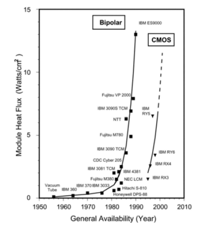
As microprocessors decrease in size, heat dissipation issues become increasingly prevalent. Moore’s law predicts the number of transistors placed on integrated circuits will double every two years. As CPUs continue to decrease in size while exponentially increasing in power each year, adequate cooling methods will increasingly become an integral part of new design planning efforts. Figure 1 shows the evolution of module-level heat flux in high-end computers over several decades. As shown, module heat flux has continued to creep upward with each passing year.
An experiment was conducted to evaluate liquid immersion cooling designed to mitigate CPU overheating through the use of a commercially available synthetic petroleum fluid, Opticool Fluid.
Issues with Air Cooling in Technical Applications
Air-cooling, which incorporates the use of fans, is currently the
prevalent method of cooling CPUs in computing environments. It has several advantages including reduced cost, relatively low noise, and is free of piping elements, tubes and cables.[2] The main function of fans is to pump air so that heat is effectively carried away from the CPU assembly. Air pressure can vary by incorporating fans in series (placed on top of one another) or parallel configurations (side-by-side).[3] The serial setup increases the discharge pressure while the parallel setup increases the area coverage. Based on several studies completed in recent years[1][2][4][5][6][7][8][9], air-cooling technology is insufficient to keep up with the growing requirements of CPU cooling in the marketplace.
Heat Transfer Overview
Fluid flow can be laminar (steady state) or turbulent, and heat might be transferred with and without phase change. In addition, the flow regime might be treated as Newtonian or non- Newtonian. Appropriate theoretical and empirical heat transfer equations have been developed for different velocity profiles, flow regimes and flow geometries. For the ideal case of fluid flow in a shell-and-tube exchanger, heat is transferred by radiation and convection to tubes via conduction through tube walls and by forced conduction from the internal wall surface to the bulk fluid.
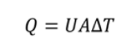 The basic equation governing all such heat transfer is where Q represents heat transferred in unit time, U represents overall heat transfer coefficient, A represents available surface area and ΔT represents temperature gradient between the source and the sink (or the inlet and the outlet). If multiple fluids or separating walls are used, then the overall coefficient U can be decomposed into individual coefficients h, each representing a particular medium.[10]
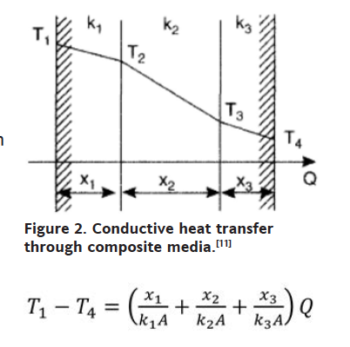
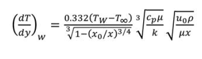
With reference to figure 2, the thermal gradient T1 – T4 is (right) where Q becomes the ratio of total driving force to total thermal resistance per unit area.[11] In instances of convective transfer, which is often the principal mechanism in liquid cooling, the heat transfer coefficient may be expressed as a dimensionless relation known as the Nusselt number, or as a dimensional equation. Convection is distinguished between natural (fluid movement caused by the transfer process itself) or forced (fluid movement caused by an externally applied force); in the former, the Nusselt number for external spaces is (left) where Ra, the Rayleigh’s number and Pr, the Prandtl number, are dimensionless numbers corresponding to the flow velocity and fluid properties.[12] 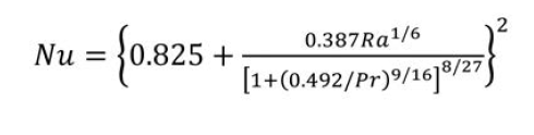 When we have steady flow of fluid past an immersed flat plate, two boundary layers develop. The first is hydrodynamic, within which velocity profile changes from 0 at the plate surface to flow velocity at the outer boundary; the second is thermal in which temperature profile changes from the plate surface temperature to the fluid temperature. These boundary layers are shown in Figure 3.
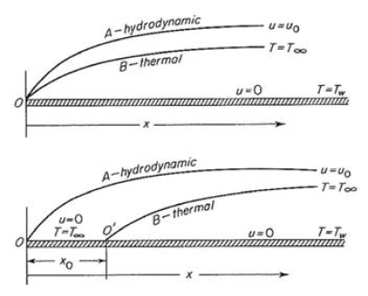
layers for steady flow of fluid past an immersed plate. Fluid temperature is T∞ and plate surface temperature is Tw; fluid velocity is u0. Entire plate is heated at top while there is an unheated length x0 at bottom.[13]
Raspberry Pi
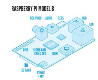
Figure 4 shows the layout of the unit. The Raspberry Pi device is representative of ways that smaller component sizes are leading to more powerful computing. The device has been used for media streaming, home automation, and robotic applications,
to name a few[14]. The Raspberry Pi is typically powered by 5 V and 1 A 1.5 A and can be overclocked to a maximum
1,000 MHz. As with other computing devices, the Raspberry Pi tends to overheat when overclocked or when excess voltage is applied to the device. The maximum operating temperature for the Raspberry Pi CPU is 85°C As this experiment was conducted, the CPU never exceeded this temperature.
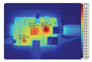
Figure 5: Thermal Image of Raspberry Pi Model B
The thermal image (Figure 5) shows that the CPU is one of the largest heat emitters when the Raspberry Pi is running at
normal capacity. During the study, CPU temperature measurements was exclusively focused on.
Experimental Design
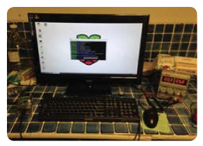
Figure 6. Raspberry Pi Model B
computing device with standard
5 V applied to power up.
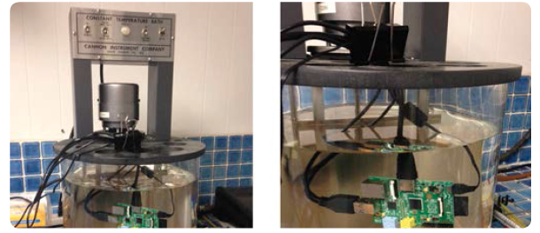
The general layout of the experimental setup used for this study is shown in Figures 6 and 7. Baseline CPU temperatures were measured with standard 5 V input while unit was overclocked at 800 MHz, 900 MHz and 1,000 MHz respectively. Laboratory temperature was maintained at 20°C throughout the duration of the experiment. The immersion fluid was maintained at this same temperature during immersion testing as well. Measurements were recorded at device startup and in subsequent one hour increments. CPU temperatures were measured for both air cooling and immersion cooling with overvoltage levels of 6 V, 7 V and 8 V applied during three hour periods for each test, respectively. Overclocking speed of 1,000 MHz was maintained for the duration of the overvoltage testing. CPU temperatures were obtained via the Raspberry Pi unit itself by using the following command sequence upon login: /opt/vc/bin/vcgencmd measure_temp ENTER.
Results
During baseline testing, 5 V was applied to the Raspberry Pi Figure 4. Diagram of Raspberry Pi during three overclocking tests. Results were as follows: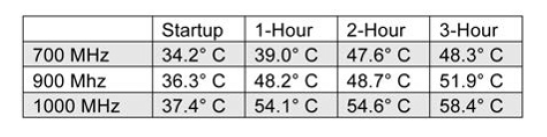
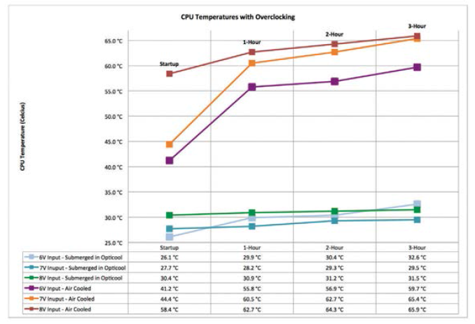
As shown, the maximum CPU temperature at 1,000 MHz after three hours of operation was 58.4°C. Next, temperatures were recorded as overvoltage was applied to the unit. Maximum overclocking of 1,000 MHz was maintained throughout. The results were recorded and graphed (Figure 8).
During 36 hours of testing, the device maintained adequate operation however when 7 V to 8 V was applied to the unit, operation became extremely unstable. This occurred during both air and liquid cooling testing. This is likely due to a limitation of the CPU used for this board, however based on these findings, on-board processor power of the Raspberry Pi can
be increased if a more powerful CPU were integrated into the design and combined with liquid immersion cooling.
Conclusion
As devices continue to shrink in size while increasing in power, performance improvements will continue to be plagued by increased power and cooling requirements. Furthermore, high temperatures negatively affect systems reliability as various components are exponentially dependent on operating temperatures. The results obtained during this experiment demonstrated how liquid immersion cooling can efficiently decrease CPU operating temperatures by as much as 50 percent or greater versus traditional air cooling. As discussed, thermal management will become increasingly important in the future. Liquid immersion cooling with Opticool is a viable solution that may be applied in any number of applications including data center environments, underwater ROVs and electric engines, to name a few.
[1] Chu, R.C.; Simons, R.E.; Ellsworth, M.J.; Schmidt, R.R.; Cozzolino, V., “Review of cooling technologies for computer products,” Device and Materials Reliability, IEEE Transactions on , vol.4, no.4, pp.568,585, Dec. 2004.
[2] Mohammed, R.K.; Yi Xia; Sahan, R.A.; Pang, Y., “Performance improvements of aircooled thermal tool with advanced technologies,” Semiconductor Thermal Measurement and Management Symposium (SEMITHERM), 2012 28th Annual IEEE, vol., no.,pp.354, 361, 18-22 March 2012.
[3] http://en.wikipedia.org/wiki/Computer_cooling
[4] Abbas, T.; Abd-elsalam, K.M.; Khodairy, K.H., “CPU thermal management of personal and notebook computer (Transient study),” Thermal Issues in Emerging Technologies Theory and Applications (ThETA), 2010 3rd International
Conference, vol., no., pp.85, 93, 19-22 Dec. 2010.
[5] Ye Li; Tong Zhengming; Huang Liping; Chen Hao, “Studies on heat transfer performances of a heat pipe radiator used in desktop PC for CPU cooling,”Materials for Renewable Energy & Environment (ICMREE), 2011 International Conference, vol.2, no., pp.2022, 2026, 20-22 May 2011.
[6] Mohammed, R.K.; Yi Xia; Sahan, R.A.; Pang, Y., “Performance improvements of air-cooled thermal tool with advanced technologies,” Semiconductor Thermal Measurement and Management Symposium, 2012 28th Annual IEEE, vol., no., pp.354, 361, 18-22 March 2012.
[7] Chu, R.C.; Simons, R.E.; Ellsworth, M.J.; Schmidt, R.R.; Cozzolino, V., “Review of cooling technologies for computer products,” Device and Materials Reliability, IEEE Transactions on, vol.4, no.4, pp.568, 585, Dec. 2004.
[8] Chien-Yuh Yang; Chun-Ta Yeh; Pei-Kang Wang; Wei-Chi Liu; Kung, E.Y.-C., “An in-situ performance test of liquid cooling for a server computer system,” Microsystems Packaging Assembly and Circuits Technology Conference (IMPACT), 2010 5th International, vol., no. pp.1, 4, 20-22 Oct. 2010.
[9] Song-Hao Wang; Guang-Yi Lee; Wei-Zhi Wang; Zhi-Yu Wang; Chyi-Shyan Tsai, “An Innovative Active Liquid Heat Sink Technology for CPU Cooling System,” Electronic Packaging Technology, 2007. ICEPT 2007. 8th International Conference on, vol., no., pp.1, 6, 14-17 Aug. 2007.
[10] Halliday, D., Resnick, R., & Walker, J. (2014). Fundamentals of Physics, 10th Ed. Chichester: John Wiley & Sons, Inc.
[11] Coulson, J. M. & Richardson, J. F. (1999). Fluid Flow, Heat Transfer and Mass Transfer, 6th Ed. Massachusetts: Butter worth–Heinemann.
[12] Maloney, J. O. (2008). Perry’s Chemical Engineers’ Handbook, 8th Ed. New York: McGraw-Hill.
[13] McCabe, W. L., Smith, J. C., & Harriott, P. (1993). Unit operations of chemical engineering, 5th Ed. New York: McGraw-Hill.
[14] Heath, N. (2012). 10 coolest uses for the Raspberry Pi. Retrieved July 14, 2014 from http://www.techrepublic.com/blog/european-technology/10-coolest-uses-for-theraspberry- pi/.
[15] Raspberry Pi Model B Schematic. Retrieved July 15, 2014 from http://www.raspberrypi.org/help/faqs/.